Difference between revisions of "How to program Xilinx CPLDs using TIAO USB Multi-Protocol Adapter (TUMPA) on Windows or Linux"

10 PCS, 10cm x 10cm, 2 layers prototype for $38.80 shipped!
(→Program CPLD) |
(→Program CPLD) |
||
| Line 145: | Line 145: | ||
</pre> | </pre> | ||
| − | The option '''-m D:\dev\cpld.data''' specifies the CPLD map file directory. If you have map files in a different, specify it by '''-m <CPLD map file location>'''. The last parameter is the jed file you wish to write to CPLD. In my case, it is trinity.jed. xc3sprog will program the jed to CPLD and verify it. | + | The option '''-m D:\dev\cpld.data''' specifies the CPLD map file directory. If you have map files in a different, specify it by '''-m <CPLD map file location>'''. '''-v''' is for verbose output. The last parameter is the jed file you wish to write to CPLD. In my case, it is trinity.jed. xc3sprog will program the jed to CPLD and verify it. |
[[Image:Xc3sprog.tumpa.xc2c64a.png]] | [[Image:Xc3sprog.tumpa.xc2c64a.png]] | ||
| Line 152: | Line 152: | ||
Now, you have successfully programmed our RGH dev board. | Now, you have successfully programmed our RGH dev board. | ||
| − | There are other commands available from xc3sprog, such as erase, read. Run xc3sprog without any parameter to print out the usage | + | There are other commands available from xc3sprog, such as erase, read. Run xc3sprog without any parameter to print out the usage: |
| + | <pre> | ||
| + | XC3SPROG (c) 2004-2011 xc3sprog project $Rev: 646 $ OS: Windows | ||
| + | Free software: If you contribute nothing, expect nothing! | ||
| + | Feedback on success/failure/enhancement requests: | ||
| + | http://sourceforge.net/mail/?group_id=170565 | ||
| + | Check Sourceforge for updates: | ||
| + | http://sourceforge.net/projects/xc3sprog/develop | ||
| + | usage: xc3sprog -c cable [options] <file0spec> <file1spec> ... | ||
| + | filespec is filename:action:offset:style:length | ||
| + | action on of 'w|W|v|r|R' | ||
| + | w: erase whole area, write and verify | ||
| + | W: Write with auto-sector erase and verify | ||
| + | v: Verify device against filename | ||
| + | r: Read from device,write to file, don't overwrite existing file | ||
| + | R: Read from device and write to file, overwrite existing file | ||
| + | Default action is 'w' | ||
| + | Default offset is 0 | ||
| + | |||
| + | style: One of BIT|BIN|MCS|IHEX|HEX | ||
| + | BIT: Xilinc .bit format | ||
| + | BIN: Binary format | ||
| + | MCS: XILINX Prom format | ||
| + | IHEX: INTEL Hex format (= MCS with bits reversed) | ||
| + | HEX: Hex dump format | ||
| + | Default for FPGA|SPI|XCF is BIT | ||
| + | Default for CPLD is JED | ||
| + | Default for XMEGA is IHEX | ||
| + | Default length is whole device | ||
| + | |||
| + | Possible options: | ||
| + | -p val[,val...] Use device at JTAG Chain position <val>. | ||
| + | Default (0) is device connected to JTAG Adapter TDO. | ||
| + | -e Erase whole device. | ||
| + | -h Print this help. | ||
| + | -I[file] Work on connected SPI Flash (ISF Mode), | ||
| + | after loading 'bscan_spi' bitfile if given. | ||
| + | -j Detect JTAG chain, nothing else (default action). | ||
| + | -l Program lockbits if defined in fusefile. | ||
| + | -m <dir> Directory with XC2C mapfiles. | ||
| + | -R Try to reconfigure device(No other action!). | ||
| + | -T val Test chain 'val' times (0 = forever) or 10000 times default. | ||
| + | -J val Run at max with given JTAG Frequency, 0(default) means max. Rate of device | ||
| + | Only used for FTDI cables for now | ||
| + | -D Dump internal devlist and cablelist to files | ||
| + | In ISF Mode, test the SPI connection. | ||
| + | -v Verbose output. | ||
| + | |||
| + | Programmer specific options: | ||
| + | -d (pp only ) Parallel port device. | ||
| + | -s num (usb devices only) Serial number string. | ||
| + | -L (ftdi only ) Don't use LibUSB. | ||
| + | |||
| + | Device specific options: | ||
| + | -E file (AVR only) EEPROM file. | ||
| + | -F file (AVR only) File with fuse bits. | ||
| + | </pre> | ||
Revision as of 19:52, 10 December 2011
Contents
Buy various JTAG cables for your Satellite Receiver, Cable Modem, Wireless Router, Standard Wiggler from http://www.easymg.com and http://www.diygadget.com
Overview
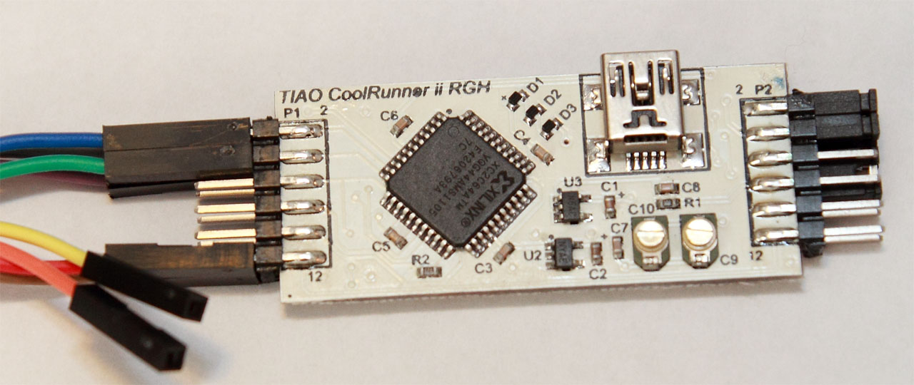
In this tutorial, I am going to show you how to program TIAO Xilinx XC2C64A CoolRunner-II CPLD Dev Board (Reset Glitch) using TIAO USB Multi-Protocol Adapter (TUMPA). This method applies to all devices supported by xc3sprog.
The process is fairly straightforward.
Required Hardware and Software
- TIAO USB Multi-Protocol Adapter (TUMPA)
- Patched xc3sprog, download from here
- Supported CPLD, we use TIAO Xilinx XC2C64A CoolRunner-II CPLD Dev Board (Reset Glitch) as our example.
- (Optional, only needed if you are programming CPLDs) Xilinx CPLD map files. It is part of Xilinx Labtools (labtools\labtools\xbr\data), or you can download from here
Software Installation
- Since I am going to program CPLD, download CPLD's map file from here. Unzip to a directory, e.g. d:\dev\.
- Install drivers for TUMPA. Instruction for Windows XP: How to install TIAO USB Multi Protocol Adapter Driver on Windows XP, Vista and Windows 7: How to install TIAO USB Multi Protocol Adapter Driver on Windows Vista or Windows 7. For Linux, you can get the driver here: FTDIDXX Drivers
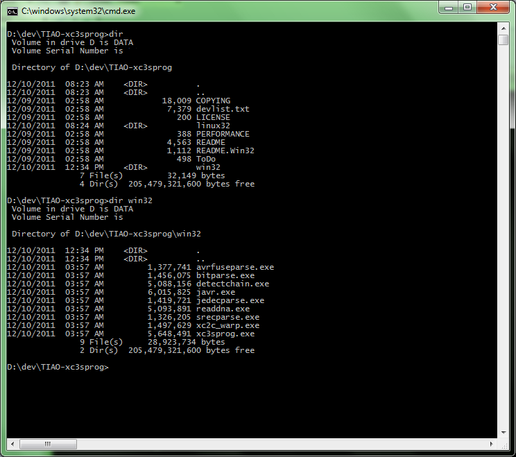
- Download TIAO patched xc3sprog from here, unzip it to a directory. In my example, I unzipped to d:\dev\ directory. After you unzip it, a directory TIAO-xc3sprog will be created. The Windows applications are under win32, Linux applications are in linux32.
Hardware preparation
In our example, we use XC2C64A (RGH Hack Dev Board), it takes +3.3V power. TUMPA provides both +5V and +3.3V, thus a separate power supply to power up CPLD is not needed.
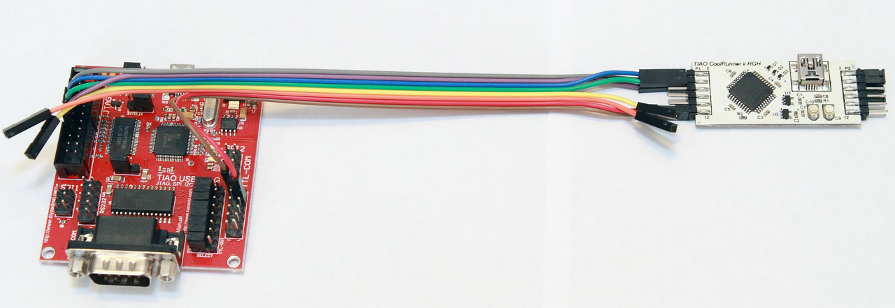
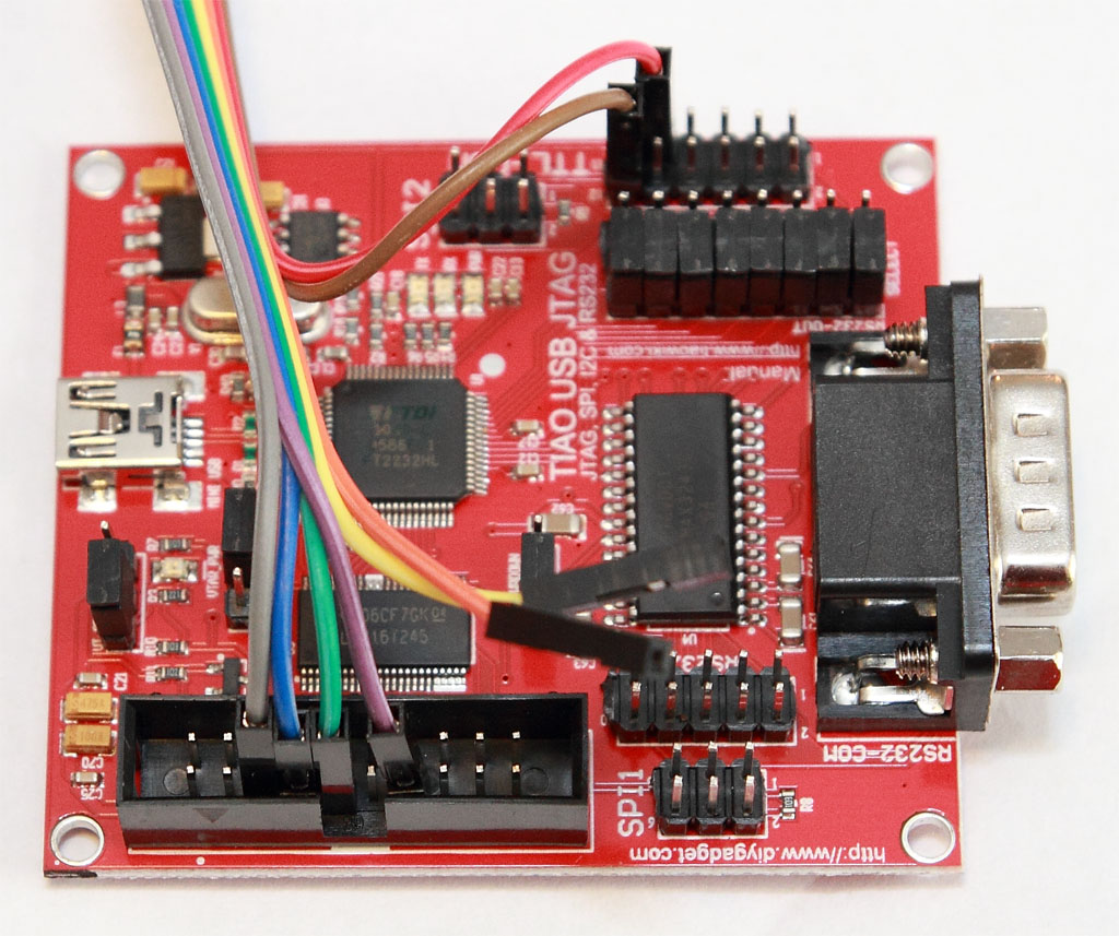
Connect TUMPA's TDI, TDO, TCK, TMS, +3.3V and GND pins to our XC2C64A dev board's TDI, TDO, TCK, TMS, +3.3V and GND respectively using the supplied female to female flexible cable.
The pinout of the JTAG connector (Complete pinout is here: TIAO USB Multi Protocol Adapter User's Manual#20 PIN JTAG Connector):
| Pin # | Description |
|---|---|
| 5 | TDI |
| 7 | TMS |
| 9 | TCK |
| 13 | TDO |
| 4, 6, 8, 10, 12, 14, 16, 18, 20 | GND |
The +3.3V and GND pin can be obtained from TTL Level Serial Connector.
Pinout of TTL Level Serial Connector (Complete pinout: TIAO USB Multi Protocol Adapter User's Manual#TTL Level Serial Connector):
| Pin # | Description |
|---|---|
| 9 | +3.3V |
| 11, 12 | GND |
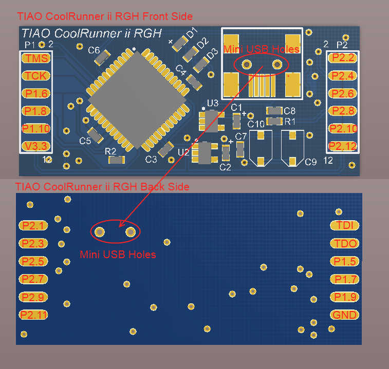
The pinout of our XC2C64A Dev Board (JTAG pins and V3.3, GND are on P1):
| Pin # | Description |
|---|---|
| P1.1 | TDI |
| P1.2 | TMS |
| P1.4 | TCK |
| P1.3 | TDO |
| P1.11 | GND |
| P1.12 | +3.3V |
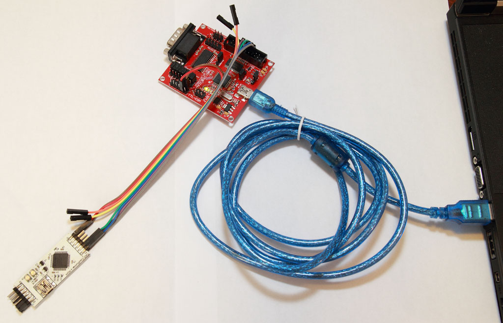
Now connect TDI, TDO, TCK, TMS, GND and +3.3V together:
Program CPLD
Copy the trinity.jed (or your jed file) to TIAO-xc3sprog\win32 or linux32 directory. In my case, I copied it to TIAO-xc3sprog\win32 directory as I am testing on Windows 7 64bit.
Connect TUMPA to PC using a USB cable:
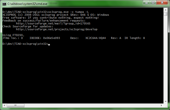
Now, open a dos prompt windows, change directory to where you have unzipped TIAO-xc3sprog\win32, run the following command to detect JTAG chain:
xc3sprog -c tumpa -L
The -c tumpa option is to specify using TUMPA JTAG adapter. The -L option is to tell xc3sprog to use FTDI's D2xx driver instead of LibUSB and LIBFTDI. This is recommended.
Your CPLD should be detected:
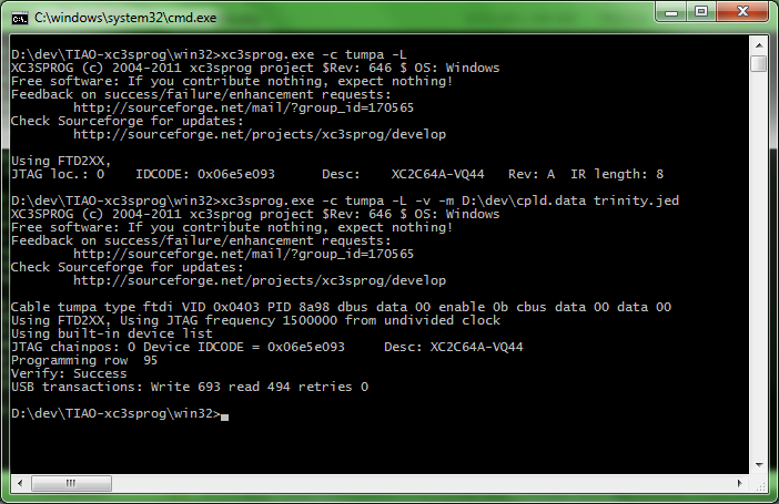
Now, run the following command to program the CPLD:
xc3sprog -c tumpa -L -m D:\dev\cpld.data trinity.jed
The option -m D:\dev\cpld.data specifies the CPLD map file directory. If you have map files in a different, specify it by -m <CPLD map file location>. -v is for verbose output. The last parameter is the jed file you wish to write to CPLD. In my case, it is trinity.jed. xc3sprog will program the jed to CPLD and verify it.
Now, you have successfully programmed our RGH dev board.
There are other commands available from xc3sprog, such as erase, read. Run xc3sprog without any parameter to print out the usage:
XC3SPROG (c) 2004-2011 xc3sprog project $Rev: 646 $ OS: Windows
Free software: If you contribute nothing, expect nothing!
Feedback on success/failure/enhancement requests:
	http://sourceforge.net/mail/?group_id=170565
Check Sourceforge for updates:
	http://sourceforge.net/projects/xc3sprog/develop

usage:	xc3sprog -c cable [options] <file0spec> <file1spec> ...
	filespec is filename:action:offset:style:length
	action on of 'w|W|v|r|R'
	w: erase whole area, write and verify
	W: Write with auto-sector erase and verify
	v: Verify device against filename
	r: Read from device,write to file, don't overwrite existing file
	R: Read from device and write to file, overwrite existing file
	Default action is 'w'

	Default offset is 0

	style: One of BIT|BIN|MCS|IHEX|HEX
	BIT: Xilinc .bit format
	BIN: Binary format
	MCS: XILINX Prom format
	IHEX: INTEL Hex format (= MCS with bits reversed)
	HEX:  Hex dump format
	Default for FPGA|SPI|XCF is BIT
	Default for CPLD is JED
	Default for XMEGA is IHEX
	Default length is whole device

Possible options:
   -p val[,val...]  Use device at JTAG Chain position <val>.
             Default (0) is device connected to JTAG Adapter TDO.
   -e        Erase whole device.
   -h        Print this help.
   -I[file]  Work on connected SPI Flash (ISF Mode),
             after loading 'bscan_spi' bitfile if given.
   -j        Detect JTAG chain, nothing else (default action).
   -l        Program lockbits if defined in fusefile.
   -m <dir>  Directory with XC2C mapfiles.
   -R        Try to reconfigure device(No other action!).
   -T val    Test chain 'val' times (0 = forever) or 10000 times default.
   -J val    Run at max with given JTAG Frequency, 0(default) means max. Rate of device
             Only used for FTDI cables for now
   -D        Dump internal devlist and cablelist to files
             In ISF Mode, test the SPI connection.
   -v        Verbose output.

Programmer specific options:
   -d        (pp only     ) Parallel port device.
   -s num    (usb devices only) Serial number string.
   -L        (ftdi only       ) Don't use LibUSB.

Device specific options:
   -E file   (AVR only) EEPROM file.
   -F file   (AVR only) File with fuse bits.
Buy various JTAG cables for your Satellite Receiver, Cable Modem, Wireless Router, Standard Wiggler from http://www.easymg.com and http://www.diygadget.com

10 PCS, 10cm x 10cm, 2 layers prototype for $38.80 shipped!
